CNC touchplate update

I’m currently working on a number of updates to my CNC machine, including upgrading to a spindle, but the post about it was getting long, so I’m breaking it into smaller chunks.

The first is this update to the touch plate, as I’ve had a couple of issues with the current one.

The first is that the magnetic probe is kind of a pain to make, as it required soldering directly to a magnet, while moving quickly enough to minimize loss of magnetism.

The second and biggest one is that, for the wire to reach from the control box to the working area, it has to be long and unruly.

New probe

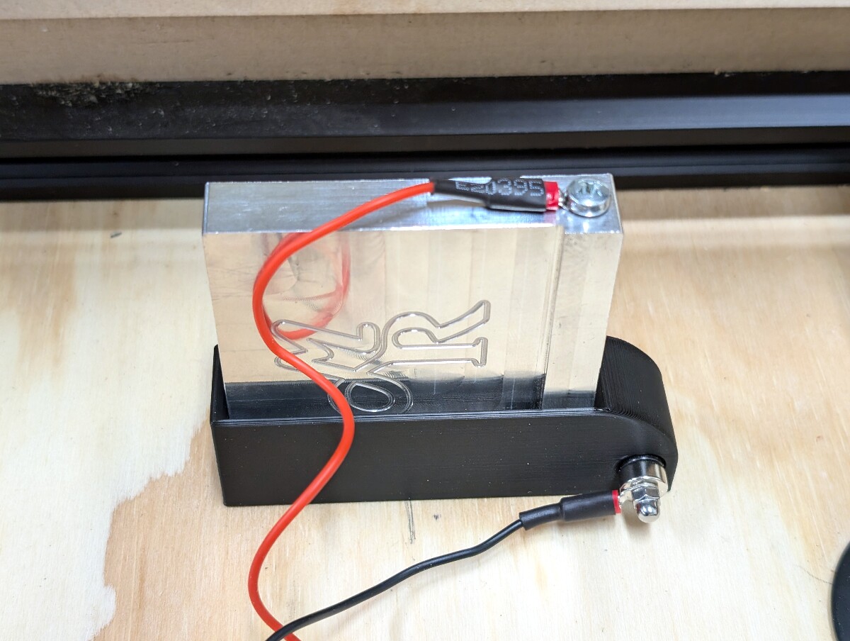
For the first issue, I’ve changed to a much easier to assemble design requiring:

  • a magnet with an m3 countersunk hole
  • an m3 flathead screw
  • a ring connector
  • an acorn nut to make it look fancy.

Now assembly just requires screwing the parts together and crimping or soldering the ring connector to the probe wire.

A magnetic probe with no wire attached
Assembled probe

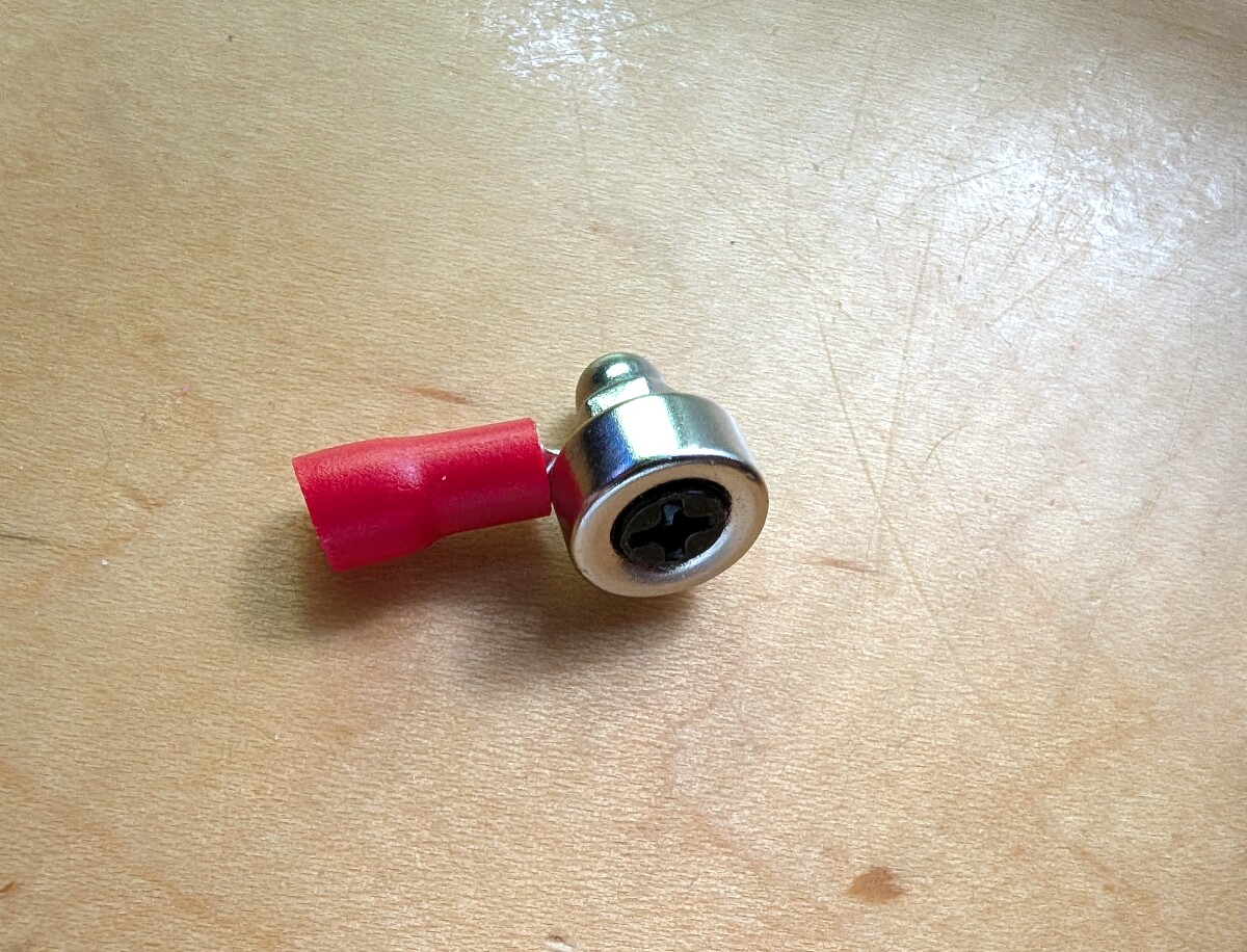
The (temporary) screw shown here has a black oxide coating making it non-conductive. This will be replaced with a steel screw before use.

New wiring

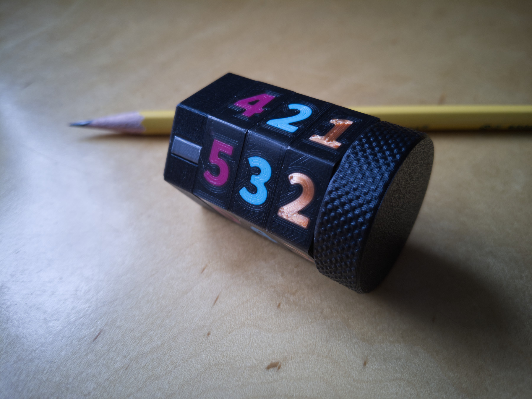
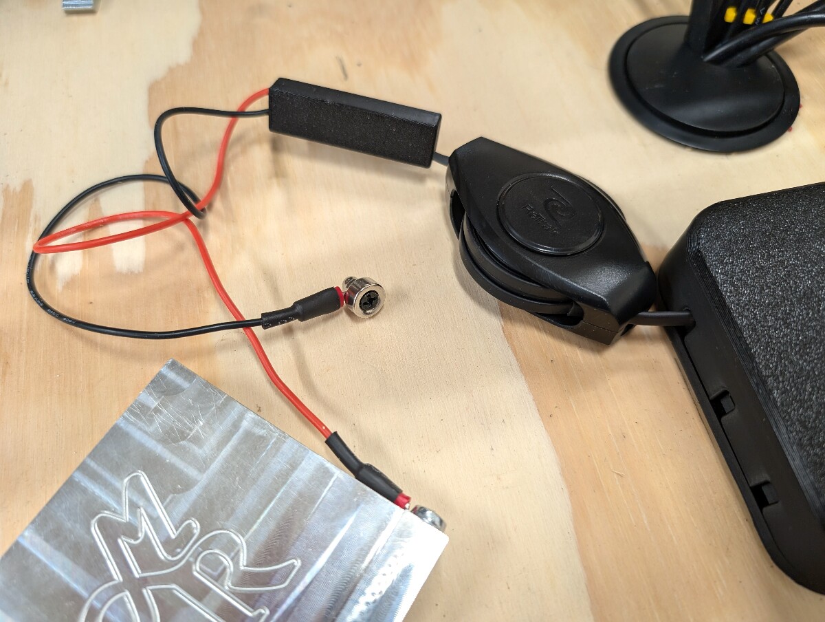
For the wire issue, I’ve replaced the bulk of the wire with a relatively long (6 foot) retractable audio cable that I found, and spliced that to a short length of flexible wire for the probe and touch plate.

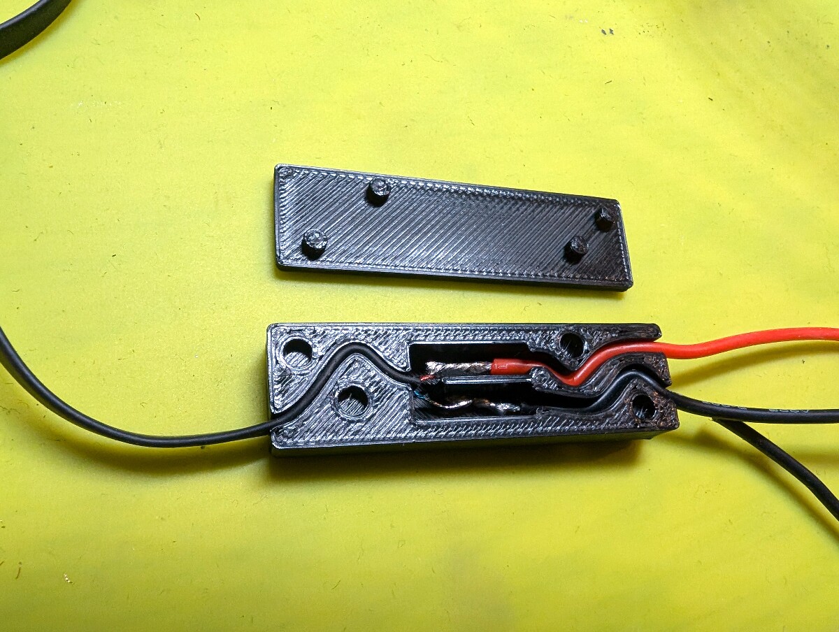
The flat audio cable in the cord retractor uses relatively fragile, enamel coated wire, which requires burning the coating off before it car be soldered. I designed and printed a cable strain relief for this end to help keep them stable when pulling the cable around.

A small (40mm) black plastic 3d-printed housing and lid, with interlocking pegs to keep the lid in place when closed. The input side of the housing has a thin serpentine channel containing a flat audio cable, the other output side has two wider channels for individual stranded wires. In between the housing has two larger separated channels where the input and output wires have been individually soldered together.
Strain relief with soldered connections

Another way to solve the wire issue would be to run a probe wire and convenient output plug through the drag chain to the spindle. Then, I’d only ever need a relatively short wire to reach the workpiece.

A cable retractor connected to a black box on one side, and a magnetic probe and touch plate on the other, with a black strain relief between them.
The finished product

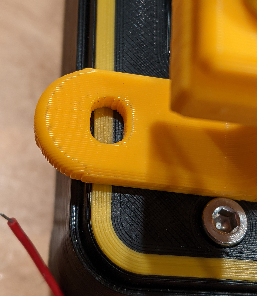
I also made a new touchplate holder that uses a bolt to give the probe somewhere to stick when not in use. You can find it, and the original probe and mount design here: https://www.printables.com/model/30072-millright-mega-v-touch-plate-holder-and-magnetic-p

A black plastic shell that the bottom of the touch plate slides into. The probe attaches magnetically to a bolt passing through the housing
3d printed touchplate holder

I’ve shared this project in a few places, but like many other projects, I’ve neglected to add it to this blog.

I’m currently using CNCjs with my GRBL-based CNC, and while there are some really nice pendants out there for 32-bit grblHAL boards, the options for physical devices and interfaces for older 8 bit boards like mine, with CNCjs, are very limited.

Previous to this, I was using another pendant I put together, cncjs-pendant-keyboardreader, using a wireless keyboard.

This supported smooth jogging, and a handful of macros and preset actions, but with no visual feedback, it was difficult to remember all of the commands and shortcuts.

I found that if I hadn’t used the machine in a while, I completely forgot which keys did what. Was it control or alt for faster jogging? How do you dismiss notifications or unpause a job? And so on.

I set out to create a more usable web interface for touch devices, with the intention of also supporting a physical Streamdeck.

The Streamdeck is interesting. At its heart, it’s a single, self-contained LCD touchscreen, with a clever approach to physical buttons. The buttons themselves are transparent, with a membrane that runs along the outside edge of the button to activate the screen when pressed, giving the illusion of multiple discrete displays.

Being self contained, you can send images in jpeg format to the device to populate the display, instead of treating it as an external monitor. This is great for my use, since I can continue to use a headless Raspberry Pi for performance.

The result is the (creatively named) cncjs-pendant-streamdeck, an obsessively configurable frontend for CNCjs with these goals in mind. The included configuration is for a 3x5 Streamdeck, but it supports both the mini (2x3) and XL (4x8). I have not tested it with newer devices with secondary display areas, since I don’t own one.

Streamdeck running cncjs-pendant-streamdeck

Out of the box, it supports:

  • Multi-axis smooth or incremental jogging. The web interface supports multitouch, so two (or more) jog direction buttons can be used at the same time.
  • Multiple pages
  • Templated text to display CNC state, like current position
  • Conditional button display/disabling
  • Custom images/colors
  • Execute macros (ex: for probing) and cncjs custom commands
  • Execute actions on press, release, or button hold
  • Display and manage alarms, holds, and pause events
  • Job selection from the CNCjs watch folder
  • Numeric input
  • (Animated) gcode rendering and thumbnails

It can be used with or without a physical Streamdeck, with nice, large buttons for use on a phone or tablet.

Web view of the cncjs-pendant-streamdeck interface

From a development perspective, the project is built as a Vue application, with a separate nodejs renderering pipeline for the Streamdeck output, and a handful of adapters to abstract the differences between the Node and Web display. This allows all of the business logic (and configuration) to be shared between the two display types.

Ideally, I’d love to build a visual configurator to generate the config file, but honestly there hasn’t really been enough interest to warrant the effort.

That said, the project is extensively documented, and I’ve published the cncjs-pendant-streamdeck-validator package, which can be used from the commandline, in a javascript project, or you can use the schema directly, so there should be enough there for somebody to build that tool if desired.


I installed Home Assistant with Dokku. It was very easy, but there were a couple of gotchas that slowed it down a bit.

Setup

Create a new homeassistant app in Dokku

dokku apps:create homeassistant

Set the timezone

dokku config:set homeassistant TZ=America/Chicago

Create a folder that will be used for Home Assistant configuration

mkdir /path/to/my-config
dokku storage:mount homeassistant /path/to/my-config:/config

Home Assistant uses its own init procedure, and we need to disable automatic init

dokku scheduler-docker-local:set homeassistant init-process false

Initialize Home Assistant app from its docker image

dokku git:from-image homeassistant ghcr.io/home-assistant/home-assistant:stable

Dokku didn’t correctly configure the correct port for the container, so:

Remove the default proxy port if needed:

dokku proxy:ports-remove homeassistant http:80:5000

Add the correct proxy port:

dokku proxy:ports-add homeassistant http:80:8123

To enable autodiscovery, Home Assistant needs to be connected to the host network. Other than autodiscovery, I had no issues using the default network and normal port mapping.

You can enable this option in dokku with

dokku docker-options:add homeassistant deploy,run "--network=host"

Once Home Assistant is on the host network, dokku’s zero-downtime restarts will fail when updating or restarting the service, because the bound port will already be in use.

Zero downtime restarting can be disabled with

dokku checks:disable homeassistant

Updating Home Assistant

To update Home Assistant, use git:from-image again, pointing to the newest SHA digest for your architecture (instead of using the :stable tag)

dokku git:from-image homeassistant ghcr.io/home-assistant/home-assistant@sha256:<shadigest>

You can get this digest from docker hub for your architecture: docker hub, or you can pull the image locally and use:

docker inspect --format='{{index .RepoDigests 0}}' ghcr.io/home-assistant/home-assistant:stable

My favorite automations (so far) turn my printer’s light off automatically after a print completes, and lets me know to open windows when the weather is cooler and less humid outside, and air quality is ok.


I do a lot of multicolor 3d printing, where more than one color is printed on the same layer using manual filament swapping, and I wanted to share some tips that I haven’t seen collected everywhere.

3d printed game counter with multiple rings with inlayed numbers, with different colors for each ring.
Several multicolor prints for a TTRPG tracker

Some of this applies to layer/height-based color swapping, but this is directed specifically at the above, AKA the poor-man’s MMU.

This is pretty easy to set up in PrusaSlicer, and probably other slicers as well, but I don’t have as much experience with them.

Setup

First, create a new printer with two (or more) configured extruders, one extruder for each color you’d like to use in your print.

In the Custom G-code tab, set the Tool change G-code value to m600.

Tool change G-code field with the value 'M600`

This triggers a manual filament change when changing extruders.

Lastly, import your multipart object, select it and press the “Split To Parts” button in the toolbar.

Next, assign the appropriate extruder to each part in the part list.

PrusaSlicer parts list with multiple items selected. Context menu is open to the Change Extruder option with Extruder 2 highlighted

Extruder 1 will be used first, so use that one for the background color, and use extruder 2 for your inlay. Otherwise you’ll end up doing an extra color swap.

Rendered gcode preview showing the underside of a part with inlayed numbers in a different filament color
Ready to go

Tip 1: Minimizing filament swaps

Without an automatic filament changer, you’ll may want to minimize the number of manual filament swaps.

For top or bottom-layer inlays, I usually stick to a total of two colors, two layers thick. This allows two-color prints with a total of two filament changes.

Additional colors add one more swap per color per layer.

number_of_swaps = layer_count * (colors - 1)

Tip 2: Filament opacity

For text inlays and similar small details, you’ll want to use a filament that is as opaque as possible. Transparent colors, especially over dark “background” colors, will appear dim and muddy.

Black box with a small yellow inlayed border, compared to another part printed entirely with the same filament. The border's color is less intense, and darker
Two 0.3mm layers of yellow-orange over black, compared to a single colored part

When using a less opaque filament, a white or light colored filament for the background will be more forgiving.

A small test print is recommended to make sure your colors will look OK at the layer thicknesses you’re using, especially if your prints are large or complex.

Tip 3: Use a wipe tower

This actually serves two purposes. Obviously, it allows a reliable color change with configurable purge volumes without as much baby sitting while changing filament, but it also has another side effect.

Without a wipe tower, the m600 filament change event will take place when the extruder has completed the last object of that color for a layer, and when that’s complete, the extruder will return to the last location, before moving on to the next object location.

This can cause a small, circular dot of the new filament color in the last object location, which can be pretty noticeable with certain colors, or when printing on the top layer.

With a wipe tower, the extruder will first be moved to the wipe tower area, then initiate swap filament, and then will return to the wipe tower for purging, which prevents the wrong-color-spot.

The tower is still very efficient for prints where the bottom layer(s) have a color change, since the wipe “tower” will only be two layers thick.

Gcode preview with short, rectangular wipe tower alongside part to be printed
Small wipe tower

Tip 4: Z-hop

On layers where there will be filament swapping, add a small Z-hop. This prevents any small blobs from getting dragged across the printed surface. This is not usually noticeable with single color prints, but can stand out more with contrasting colors. The z-hop setting prevents this by raising the extruder up a little bit for travel moves.

In PrusaSlicer, this is configured per extruder (so you’ll need to set it more than once) under Printer Settings -> Extruder x, under “Lift Z”. You’ll need to enable retraction if you don’t already, or the setting will be disabled. You can limit the range where Lift Z is enabled in the setting below it.

PrusaSlicer retraction printer settings. Lift Z is set to 0.2mm, between the range of 0 and 0.6mm Z heights
Lift Z Settings
Gcode preview with travel moves displayed, with visible vertical moves when traveling to and from colored sections
Lift travel moves

The word hello centered inside a circle in CascadeStudio

I’ve been using CascadeStudio recently for parametric modeling (like this) and needed a way to center some dynamic text, which isn’t implemented currently.

Fortunately, a user on github documented a way to get the boundary box of a solid shape here: this discussion post, which makes centered (or right-aligned) text easy.

// https://github.com/zalo/CascadeStudio/discussions/86#discussioncomment-506883
const getBounds = shape => {
    const bmin = { x: Infinity, y: Infinity, z: Infinity },
        bmax = { x: -Infinity, y: -Infinity, z: -Infinity };

    ForEachFace(shape, (index, face) => {
        ForEachVertex(face, (vertex) => {
            const pnt = oc.BRep_Tool.prototype.Pnt(vertex);
            const x = pnt.X(), y = pnt.Y(), z = pnt.Z();

            if (x < bmin.x) bmin.x = x;
            if (y < bmin.y) bmin.y = y;
            if (z < bmin.z) bmin.z = z;

            if (x > bmax.x) bmax.x = x;
            if (y > bmax.y) bmax.y = y;
            if (z > bmax.z) bmax.z = z;
        });
    });
    return [bmin, bmax];
}

// create the text shape
const textShape = Text3D("hello!", 10, 0.1);

// get the minimum and maximum bounds for the text
const [min, max] = getBounds(textShape);
const width = max.x - min.x;
const height = max.z - min.z;

// translate the text by half the width and height
Translate(
    [-width / 2, 0, -height / 2],
    textShape,
    false);

Demo link