Note: This is an older (2+ years old) project, and there are now better third party options available (check Millright groups on facebook), even completely replacing both the Z plate and router mount with significantly beefier aluminum parts free of these issues.
There are a couple of problems with the default router mount on this CNC.
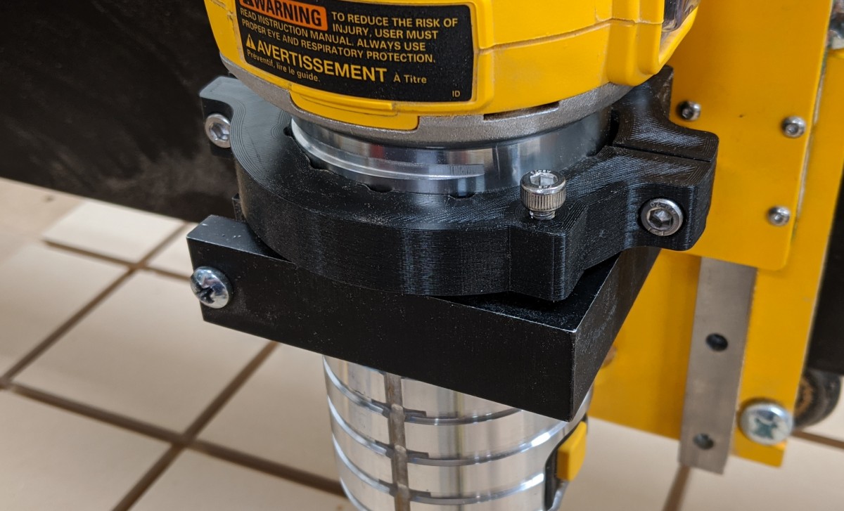
The first is that none of its sides are parallel. When mounted to the Z-axis plate, it visibly dives downward in the front toward the spoilboard.
The surfaces that contact the router are also tapered inward, so any adjustment to the router clamping has a tendency to shift the router in one direction or another.
Both of these issues can be shimmed (somewhat), but since the router mount bolts through the Z plate from behind, it takes a lot of work to disassemble the Z axis, loosen the router mount, shim behind it, tighten back up, and reassemble before checking tram again.
The first pass I made at fixing this used a 3d-printed collar, positioned above the router mount with a few adjustable screws to adjust the offset. The idea was that the collar could be tightly fastened to the router, adjusted, and held down firmly while tightening the router mount’s clamp to make fine adjustment more reliable. This helped, but ultimately not enough. I think this could have worked with an aluminum collar, and with holes threaded from the top into the router mount so that manual downward pressure wasn’t required.

In the end, I replaced the stock router mount with this (well machined) OpenBuilds router mount instead. The diameter is slightly oversized for the DWP611 router I’m using, so I 3d-printed a thin (~1-2 mm) straight shim for it.
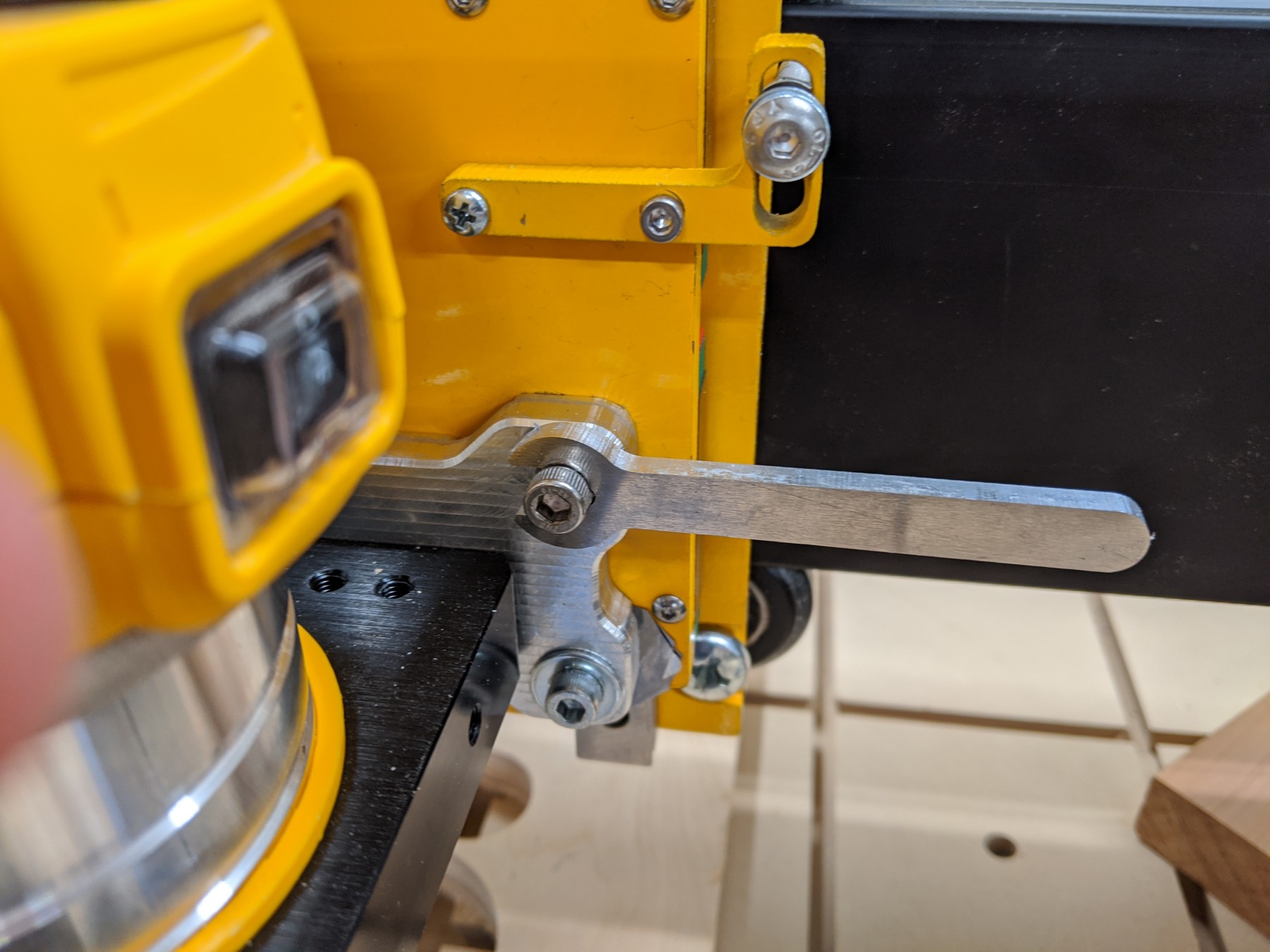
To mount this to the router, and allow easier tramming in both the X and Y axes, I’ve designed this plate that will bolt to the Z-plate through the front. This allows shimming in the Y axis by just loosening the plate from the front, adding shims, and tightening back down.

For the X axis, I’ve added overside holes to allow the use of eccentric nuts for adjustment.
This did require drilling and tapping 4 new holes in the stock steel Z-plate, but that went fine going slow and careful (and using a drill press to keep the tap straight).
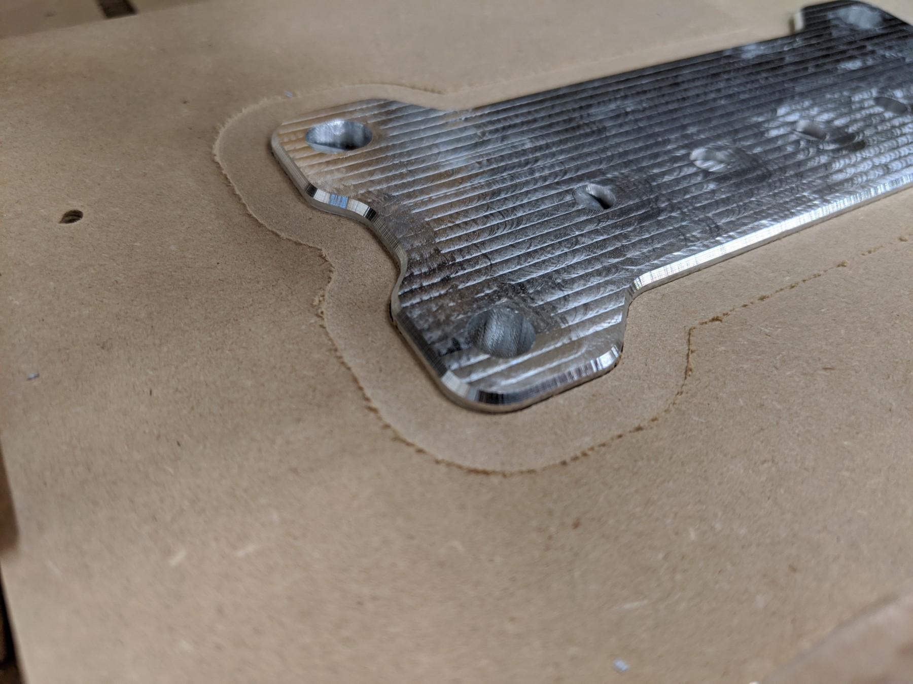
Here’s the first side cut from 3/8” aluminum. As this is a (not yet installed) tramming plate, please excuse the surface finish.

To cut the opposite side to size, and chamfer the edges, I cut a pocket in scrap MDF both for workholding and to position the part. This mostly worked but I did end with a small gouge on one side, when (I think) the part shifted a little bit.

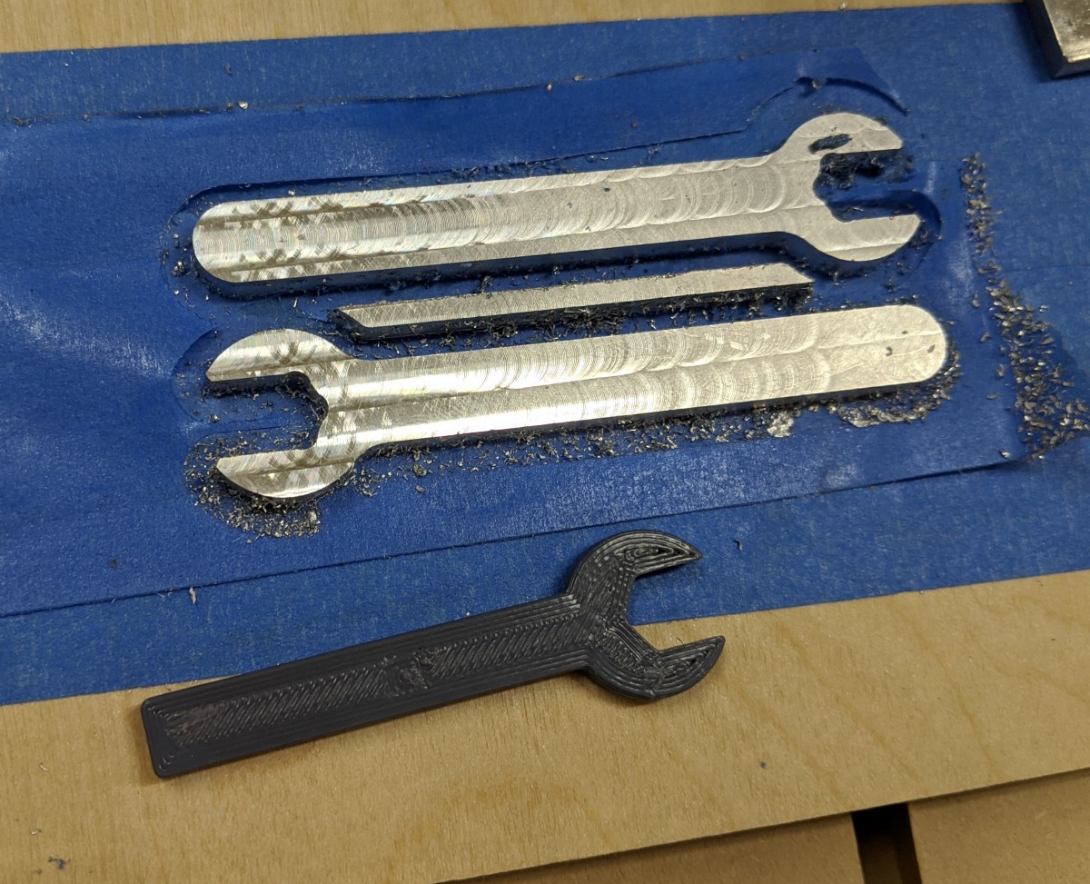
I also cut these two tiny wrenches to help adjust the eccentric nuts.


Overall, this has made a huge improvement in the time required for tramming/squaring and I’d highly recommend it (or replacing the stock Z plate entirely) if you’re having similar issues.
